


Volume 22, No.4 Pages 297 - 305
1. 最近の研究から/FROM LATEST RESEARCH
From the Research of Contract Beamline ~BL12B2/12XU(NSRRC)~
Developed in-situ X-ray Spectroscopy to Investigate the Catalyst System toward Oxygen Evolution Reaction
Department of Chemistry, National Taiwan University
- Abstract
- Oxygen evolution reaction (OER) is a half reaction of water splitting. Toward this end, transition-metal oxides have been demonstrated to act as electrocatalysts for OER. Among various transition-metal oxides, 3d transition metals with spinel structures were widely used for being active electrocatalysts toward this reaction. Nevertheless, spinel is a complex structure, in which two oxidation state of metal ions as well as two different crystallographic sites are present in this structure. To investigate the behavior of spinel structure during OER, we have developed both in-situ X-ray absorption spectroscopy and in-situ grazing-angle X-ray diffraction manner, while various well-designed samples were prepared to figure out the dominated factors step by step. First, we have modified the electrocatalysts with surface reversibly adapting layer to improve the resulting stability. Second, we choose the spinel structure with bimetallic system of NiCo2O4 to reveal the active cite between these two metals. Furthermore, the non-active metals were employed to substitute for the divalent and trivalent metal ions in spinel to point out the active centers. The effects of crystallographic sites were verified by a model system of inverse spinel Fe3O4 with replacing by Co, Ni, and Zn divalent metal ions. As a result, we can clarify that the divalent metal ions are the active center for OER in the spinel structure, while a phase transformation to metal oxyhydroxide which act as the real active phase is needed to achieve a higher performance. From the result of understanding spinel behavior toward OER, we can realize that the in-situ X-ray spectroscopy is a useful technique, and believed that this technique can be used not only in spinel structure but other catalyst for other reactions.
Introduction
People have relied on carbon-based fuel to produce electricity for many year, but these carbon-based fuels will run out within years[1][1] Rogner, H. H.: Annu. Rev. Energy Environ. 22 (1997) 217-262.. On the other hand, carbon dioxide which is a main factor for inducing the greenhouse effect is a by-product during burning of carbon-based fuel[2][2] Bert, G. D. a.; Miquel, A. G.-M.; Steve, P. L.: Annu. Rev. Plant Physiol. Plant Mol. Biol. 48 (1997) 609-639.. Therefore, finding renewable sources to replace fossil fuel has become the most imperative thing. There are various alternatives to approach this goal such as solar energy, hydrogen through solar water-splitting, tidal energy, and wind power. Among these renewable energy, solar water-splitting is highly desired direction because its high efficiency to convert solar energy into hydrogen gas and oxygen gas[3-5][3] Khan, S. U. M.; Al-Shahry, M.; Ingler, W. B.: Science 297 (2002) 2243-2245.
[4] Kudo, A.; Miseki, Y.: Chem. Soc. Rev. 38 (2009) 253-278.
[5] Bard, A. J.; Fox, M. A.: Acc. Chem. Res. 28 (1995) 141-145..
Water splitting reaction is combined by two half reactions including the hydrogen evolution reaction (HER, 2H2O + 2e− → H2 + 2OH−) and the oxygen evolution reaction (OER, 2H2O → O2 + 4e− + 4H+)[6][6] Walter, M. G.; Warren, E. L.; McKone, J. R.; Boettcher, S. W.; Mi, Q.; Santori, E. A.; Lewis, N. S.: Chem. Rev. 110 (2010) 6446-6473.. Although only hydrogen gas generated at the cathode is energy storage substance, oxygen gas generated at the anode still need to be remarkably considered. Because OER is the kinetic barrier for driving water splitting reaction, which contains a four-electron transfer process while HER involves a two-electron transfer[7][7] Suen, N. T.; Hung, S. F.; Quan, Q.; Zhang, N.; Xu, Y. J.; Chen, H. M.: Chem. Soc. Rev. 46 (2017) 337-365.. Accordingly, the OER requires a higher overpotential to overcome the kinetic barrier for completing the oxygen evolution. In recent years, variety of metal oxides were used as electrocatalysts for OER. Among these catalysts, RuO2 and IrO2 can performe the lowest overpotentials with the values of 0.36 V and 0.4 V and showed Tafel slopes of 55 and 91 mV/dec, respectively[8][8] Lee, Y.; Suntivich, J.; May, K. J.; Perry, E. E.; Shao-Horn, Y.: J. Phys. Chem. Lett. 3 (2012) 399-404.. However, these two oxides are made of precious metals and unstable in the alkaline condition. As a consequence, many research groups are developing the earth-abundant materials with 3d transition metal oxides to achieve the goals of both stability and activity toward the OER[9,10][9] McCrory, C. C. L.; Jung, S.; Peters, J. C.; Jaramillo, T. F.: J. Am. Chem. Soc. 135 (2013) 16977-16987.
[10] Suntivich, J.; May, K. J.; Gasteiger, H. A.; Goodenough, J. B.; Shao-Horn, Y.: Science 334 (2011) 1383-1385..
Within 3d transition metal oxides, spinel-type metal oxides have exhibited highly potential toward OER due to its high conductivity and stability in alkaline condition. The spinel with a formula of AB2O4[11][11] Sickafus, K. E.; Wills, J. M.; Grimes, N. W.: J. Am. Chem. Soc. 82 (1999) 3279-3292. is a complex system, where one divalent (A2+) metal ions and the other two metals with trivalent (B3+) character are present. A and B atoms can be group 2, group 13, and first-row transition metals, while two crystallographic site, octahedral (Oh) and tetrahedral (Td) sites, are in this structure (Figure 1). Moreover, there are two possible combinations, in which one is normal spinel (A2+Td)(B3+Oh)2O4 (divalent cation A2+ in tetrahedral site) and the other one is inversed spinel (A2+Oh)(B3+Td)(B3+Oh)O4 (divalent cation A2+ in octahedral site). With the aim of realizing the key factors for active electrocatalysts toward OER in spinel system, it's essential to significantly consider both chemically oxidation state (divalent and trivalent) and two crystallographic sites in the structure. For these reasons, it's great challenge to recognize the role of metal ions upon the activity toward OER in spinel system.
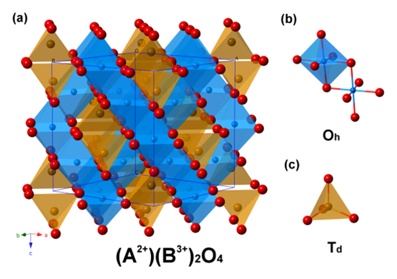
Figure 1 Crystal structure of inverse spinel AB2O4 and corresponding octahedral site (Oh) and tetrahedral site (Td).
Zhang et al. have used an in-situ FTIR (Fourier-Transform Infrared Spectrometer) experiment to reveal that -OOH group would be formed on the surface of spinel Co3O4 during OER[12][12] Zhang, M.; de Respinis, M.; Frei, H.: Nat. Chem. 6 (2014) 362-367.. It has pointed out a fact that the surface condition is much different from that of inner part of catalyst. And the surface should be a key toward the activity during OER[13][13] Man, I. C.; Su, H.-Y.; Calle-Vallejo, F.; Hansen, H. A.; Martínez, J. I.; Inoglu, N. G.; Kitchin, J.; Jaramillo, T. F.; Nørskov, J. K.; Rossmeisl, J.: Chem. Cat. Chem. 3 (2011) 1159-1165.. Additionally, the -OOH group can be observed only during the reaction undergoing. Thus, it is necessary to develop an in-situ technique for fully understanding how the electrocatalysts work during the reaction.
Methodology
Since X-ray technique is a powerful method for characterizing the nature of materials. We designed a liquid cell made of Teflon for collecting the X-ray elastic/inelastic scattering with applying a voltage at the same time. A liquid cell as show in Figure 2 was designed for in-situ X-ray absorption spectroscopy (XAS). The X-ray-light source aimed at the working electrode, and the Lytle detector was collect the fluorescence signal at the location of 90 degrees. It is really a useful method to characterize the nature of materials by XAS. By utilizing the in-situ set up, it will become more helpful to realize the alternative of oxidation states and the change of the coordination shell. In the case of in-situ X-ray diffraction, we created a window on the liquid cell to collect the diffraction patterns by using a Kapton tap to prevent the liquid from flowing out, in which a three-electrode system is performed for electrochemical testing and the FTO (Fluorine-doped Tin Oxide) acts as substrate of work electrode. Because the reaction should occur at the interface between the electrocatalysts and electrolyte, more information can be obtained at the top of side which load samples. Otherwise, it's well-known that the reactions happened only on the surface of electrocatalyst, we utilized a grazing-angle X-ray diffraction to maximize the contribution from the surface of electrocatalysts (as shown in Figure 3)[14][14] Tung, C.-W.; Hsu, Y.-Y.; Shen, Y.-P.; Zheng, Y.; Chan, T.-S.; Sheu, H.-S.; Cheng, Y.-C.; Chen, H. M.: Nat. Comm. 6 (2015) 8106.. Both in-situ X-ray absorption and X-ray diffraction experiments were collected at BL12B2, and recently we also conducted this set up at BL12XU of SPring-8.
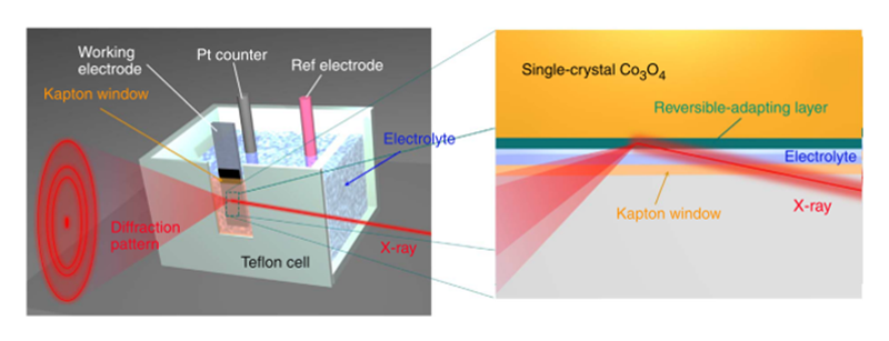
Figure 2 Schematic representation of the in-situ grazing-angle X-ray diffraction apparatus applied to a liquid electrochemical cell.
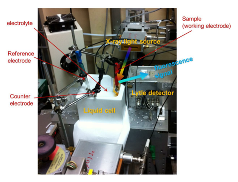
Figure 3 Digital photograph of a hand-made chemical cell for use in-situ X-ray absorption measurement.
Result
In first case, we designed single crystal Co3O4 nanocubes to investigate the behavior during OER. Single crystal can significantly rule out the influence of defects and avoid self-oxidizing. Furthermore, we reduced the surface Co3O4 into CoO with sodium borohydride (Co3O4@CoO)[14][14] Tung, C.-W.; Hsu, Y.-Y.; Shen, Y.-P.; Zheng, Y.; Chan, T.-S.; Sheu, H.-S.; Cheng, Y.-C.; Chen, H. M.: Nat. Comm. 6 (2015) 8106. because of a higher activity of rock salt CoO than that of spinel during the OER[15][15] Trotochaud, L.; Ranney, J. K.; Williams, K. N.; Boettcher, S. W.: J. Am. Chem. Soc. 134 (2012) 17253-17261.. In terms of the electrochemical performance, metal oxides were tested by linear scanning voltammetry (LSV) with corresponding Tafel plots. Co3O4@CoO sample shown a comparable performance as compared to that of RuO2 and IrO2 that performed low overpotentials as we mentioned above. The activity of OER usually compares at a current density of 10 mA/cm−2, because this value represented a 10% efficiency of solar- to-fuel conversion. Co3O4@CoO samples reached this current density at 0.430 V, while RuO2 and IrO2 with the value of 0.411 V and 0.358 V, respectively. It showed that Co3O4@CoO sample performed almost the same value to these two catalyst. Although the Tafel slope of Co3O4@CoO sample is not the lowest one among 3d transition metal oxides, it can also present high activity at neutral condition, as show in Figure 4.
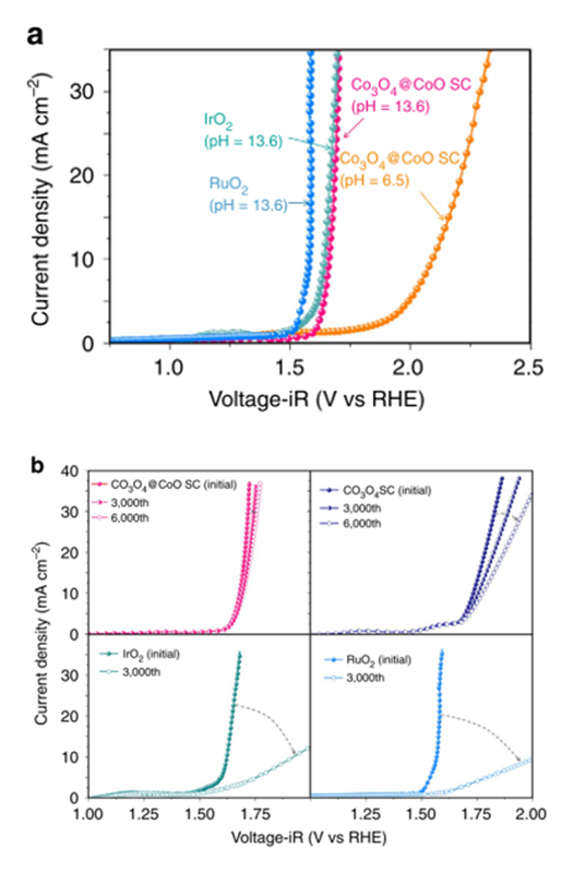
Figure 4 (a) LSV curves of Co3O4@CoO in alkaline (0.5 M KOH; pH = 13.6) and neutral (0.5 M Na2SO4; pH = 6.5) conditions, commercial RuO2 catalysts (0.5 M KOH; pH = 13.6), and IrO2 catalysts (0.5 M KOH; pH = 13.6). (b) LSV curves of Co3O4@CoO, Co3O4, IrO2, and RuO2 catalysts subjected to continual potential cycling between 1.0 and 2.0 V (versus RHE) in 0.5 M KOH for 3,000 (and 6,000) cycle measurements.
For the in-situ XAS experiment result (Figure 5), we can observe several coordination shells in Co3O4@CoO sample. In the low potential we applied (below +1.7 V versus RHE; Reversible Hydrogen Electrode), three shells can be obtained in the extended X-ray absorption fine structure spectra (EXAFS). First shell appeared at ~ 1.5 Å, second and third shells were at ~ 2.5 and 3.1 Å, respectively. For the spinel structure, the first shell is the scattering with the closet oxygen (Co-O), the second and third ones are both the scattering with two cobalt (Co-Co). The second shell with the Co-Co distance at ~ 2.5 Å can be referred to Co(III)-Co bond with octahedrally coordinated Co atoms in a normal spinel structure. The third shell represented Co(II)-Co bonds with tetrahedrally coordinated Co atoms. However, the most interesting thing was at ~ 3.8 Å once we applied higher potential (over +1.7 V versus RHE). There is a new peak can be observed, this peak could be a new Co-O scattering path which can be attributed to the formation of cobalt oxyhydroxide. Thus, we can suggest that the CoO on the surface of Co3O4 should transfer to cobalt oxyhydroxide during OER.
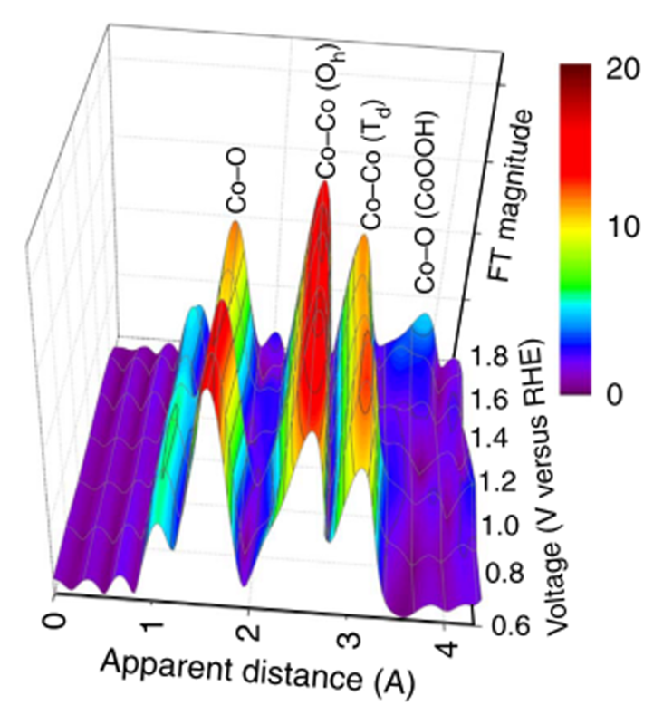
Figure 5 Voltage-dependence Fourier transform extended X-ray absorption fine structure spectra of a Co3O4@CoO in an alkaline aqueous solution containing 0.5 M KOH (pH = 13.6) and in an in-situ liquid cell.
The result of in-situ grazing-angle X-ray diffraction (Figure 6) showed that the characteristic peaks of spinel structure, and no CoO phase can be observed. Once we applied higher voltage, we can notice that the β-CoOOH formed at the lower angle (Q = 1.4 Å–1)[16][16] Butel, M.; Gautier, L.; Delmas, C.: Solid State Ionics 122 (1999) 271-284.. Once a higher voltage was applied, another phase, α-CoOOH, would also generate. Apparently, this behavior happened both in alkaline and neutral environments. This is the first direct evidence to prove the formation of metal oxyhydroxide during oxygen evolution. To combine with results of XAS, we can confirm that the CoO layer on the surface would transfer into an active phase (metal oxyhydroxide). Furthermore, in the case of a cycled potential between +2 V and +0.1 V versus RHE, metal oxyhydroxide, the active phase, appeared at high voltage and disappear at low voltage (Figure 6b). It was worth to find that metal oxyhydroxide would produce again when the voltage increased to the higher one, which referred to a fact that the CoO layer as a junction layer that could alter this structure reversibly between amorphous and metal oxyhydroxide. Due to the presence of this junction layer, it can protect the inner structure and adapt to the environment with bias for providing a more stable electrocatalyst for oxygen evolution reaction[14][14] Tung, C.-W.; Hsu, Y.-Y.; Shen, Y.-P.; Zheng, Y.; Chan, T.-S.; Sheu, H.-S.; Cheng, Y.-C.; Chen, H. M.: Nat. Comm. 6 (2015) 8106..
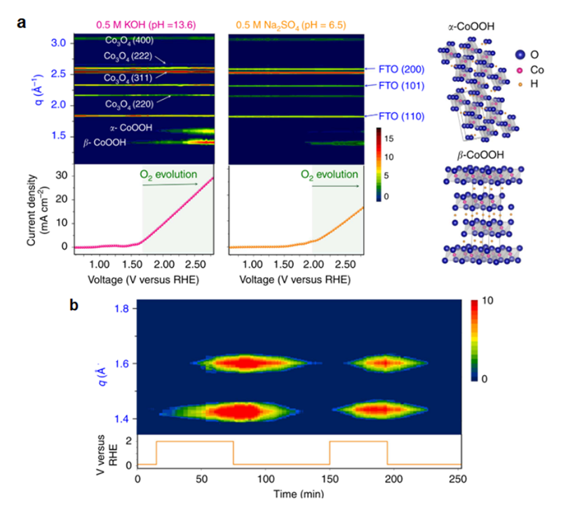
Figure 6 (a) Contour plots of in-situ grazing-angle X-ray diffraction signals of a Co3O4@CoO in an aqueous solution containing 0.5 M KOH (pH = 13.6) and 0.5 M Na2SO4 (pH = 6.5). The images show the diffraction intensity (colour coded) as a function of voltage, and data collection was performed at the NSRRC synchrotron facility by using 12 keV of energy. The lower curves show the measured current density in both cases. (b) Contour plots of in-situ grazing-angle X-ray diffraction signals of a Co3O4@CoO in an alkaline aqueous solution under switching of voltage (between 2.0 and 0.1 V versus RHE), and data collection was performed at the synchrotron facility by using 10 keV of energy to achieve better position distinguishability.
As we mentioned above, the spinel system is a complex system, where both Co3O4@CoO and Co3O4 are metal oxides with single metal element. It will be necessary to design the electrocatalysts that can individually study the roles of metal ions. According this, we introduced nickel ions into spinel structure to obtain the NiCo2O4 for investigating the active site of spinel structure. Nickel(II) is the most stable state in common metal oxides, so it can substitute for the Co(II) in the Co3O4 structure while the NiO is also a good electrocatalyst for OER[17][17] Subbaraman, R.; Tripkovic, D.; Chang, K. C.; Strmcnik, D.; Paulikas, A. P.; Hirunsit, P.; Chan, M.; Greeley, J.; Stamenkovic, V.; Markovic, N. M.: Nat. Mater. 11 (2012) 550-557.. NiCo2O4 is a normal spinel structure, which means that Ni located at tetrahedral site of spinel structure. In this case, the individual role of metal ions can be much easier clarified the factor toward OER between two metal ions. As a consequence, to realize the active site in NiCo2O4 structure, in-situ XAS is a good manner to achieve the goal that individually investigate the behaviors of Co and Ni ions through studying the corresponding X-ray absorption spectra. For the result of in-situ X-ray absorption near edge structure (XANES), the spectra of Ni K-edge changed with increasing the applied potential in 1 M NaOH (Figure 7). Initially, the energy position of absorption-edge is located in 8,350.2 eV. After increasing the applied voltage, the energy shifted to a higher value of 8,350.7 eV with continuously decreasing the intensity of white line. It indicated that the oxidation state increased during OER, and this increase in oxidation state could be referred to the formation of NiOOH. On the other hand, the energy position of Co K-edge presented a constant value (~ 7,729.3 eV) as illustrated in Figure 7b during the water oxidation. It suggested that the environment of Co ions did not change during the reaction. For EXAFS spectra of Ni ions (Figure 8), the first path is the Ni-O scattering path, and the distance of Ni-O path is around 1.5 Å. The second path with the distance of 2.5 Å is the Ni-Co(Oh) scattering. Notably, the second path decreased once the bias was applied. It could be the oxidation from Ni2+ to Ni3+, which led to a decrease in the radii of Ni ions. Besides, the EXAFS spectra of Co ions showed three paths at 1.5 Å, 2.5 Å, and 3.0 Å. Three paths could be attributed to the Co-O, Co-Co(Oh), and Co-Ni(Td), respectively. The only path that referred to Ni ions has changed as showed in Figure 8b. Consequently, the Ni ions might be the active site in NiCo2O4, while the Co ions in this structure seem to be the minor roles toward the catalytic reaction. Thus, we can realize that various metal atoms might act as different roles during OER. But there is still something unclear, it need to confirm that either the structural site or the oxidation state dominate the activity of OER[18][18] Wang, H. Y.; Hsu, Y. Y.; Chen, R.; Chan, T. S.; Chen, H. M.; Liu, B.: Adv. Energy Mater. 5 (2015) 1500091..
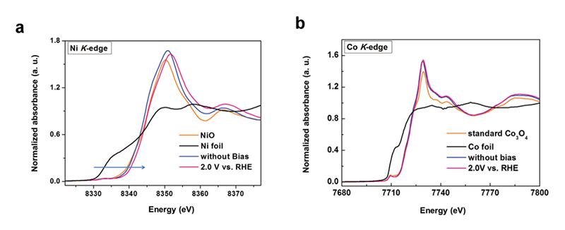
Figure 7 Normalized in-situ (a) Ni K-edge and (b) Co K-edge XANES spectra for NiCo2O4 electrode with and without applied bias in 1 M NaOH.
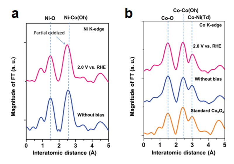
Figure 8 EXAFS oscillations extracted from in-situ (a) Ni K-edge and (b) Co K-edge EXAFS spectra for NiCo2O4 with and without applied bias in 1 M NaOH.
To recognize the influence from oxidation state, both Zn(II) and Al(III) ions that were well-known as non-active metal ions for OER were employed to replace the Co(II) and the Co(III) in Co3O4, respectively. For the activity of OER, cobalt oxide and substituted cobalt oxides were tested by both cyclic voltammetry (CV) and to obtain the Tafel plots. CV curves showed that the activity of CoAl2O4 was similar to that of Co3O4 and ZnCo2O4 was much different from the others (Figure 9a). This behavior also performed a similar trend in Tafel slope. The Tafel value of ZnCo2O4 was 113 mV/dec which was higher than that of both CoAl2O4 and Co3O4 (around 60 mV/dec). The result from electrochemistry indicated that the metal ions with oxidation state of +2 were going to dominate the performance. CoAl2O4 containing Co(II) can perform a higher activity as compared with ZnCo2O4 and was similar to that of Co3O4. In contract, ZnCo2O4 lacks of Co(II) and leads to a lower activity than the others. Additionally, the in-situ XAS clarified a similar trend to the observations from electrochemistry. The first difference recognized from EXAFS spectra was only two coordination shells in CoAl2O4 while there are three coordination shells in both ZnAl2O4 and Co3O4 (Figure 10a-c). The first shell with a distance of 1.5 Å should be the Co-O scattering path, and the second path (2.5 Å) which CoAl2O4 sample lacked was the scattering path of Co-Co(Oh). The last one was the paths of Co-Co(Td), Co-Zn(Td), and Co(Td)-Al. It verified that all of these samples were normal spinel, wherethe metal ions with oxidation state of +2 occupied the tetrahedral site in the structure. Once the voltage was applied, the first shell of both CoAl2O4 and Co3O4 that contained Co(II) ions has changed while the ZnCo2O4 stayed in the same place during the reaction (Figure 10d). The XANES also reveal a different behavior between ZnCo2O4 and CoAl2O4 samples (Figure 10e and f). The white line intensity of CoAl2O4 sample would change when voltage was applied. As mentioned above, the peak shift could refer to the oxidization of metal. The Co(II) within both CoAl2O4 and Co3O4 samples would form CoOOH. That's the reason why a higher performance of CoAl2O4 and Co3O4 than that of ZnCo2O4. As a result, the active site in the spinel structure can be clarified as the divalent metal ions. The divalent metal of CoAl2O4 and Co3O4 was Co(II), while the divalent metal ions of ZnCo2O4 was Zn(II) that has been reveal to be inactive for OER[19][19] Wang, H.-Y.; Hung, S.-F.; Chen, H.-Y.; Chan, T.-S.; Chen, H. M.; Liu, B.: J. Am. Chem. Soc. 138 (2016) 36-39..
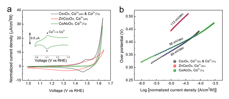
Figure 9 Electrochemical performance toward OER. (a) Cycling voltammetry curves and (b) corresponding Tafel slopes for Co3O4, ZnCo2O4, and CoAl2O4.
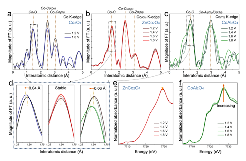
Figure 10 In-situ X-ray absorption spectroscopy. (a−c) Co K-edge EXAFS spectra for Co3O4, ZnCo2O4, and CoAl2O4, where the applied voltage is referenced to RHE. (d) Enlarged Co K-edge EXAFS spectra Co−O interatomic distance for Co3O4 (blue), ZnCo2O4 (red), and CoAl2O4 (green). (e and f) Normalized in operando Co K-edge XANES spectra for ZnCo2O4 and CoAl2O4.
On the other hand, the effects of different crystallographic sites need to be further confirmed. Toward this end, Fe3O4 with an inverse spinel structure has been utilized as a model system. The electronic configuration of iron is d5, and the energy difference is small between octahedral site and tetrahedral site. So the iron ions can possibly occupy both two sites. Based on the crystal-field theory and linear muffin tin orbital (LMTO) calculation, most of the divalent M2+ ions prefer occupying octahedral sites rather than tetrahedral positions[20][20] Szotek, Z.; Temmerman, W. M.; Ködderitzsch, D.; Svane, A.; Petit, L.; Winter, H.: Phys. Rev. B 74 (2006) 174431.. Co, Ni, and Zn ions substituted for the divalent metal ions in the Fe3O4. For the electrochemical result, LSV results showed that both CoFe2O4 and NiFe2O4 have a higher performance than the others (Figure 11a). The oxidation peak can be only observed in CoFe2O4 and NiFe2O4 samples (Figure 11a, insert), while Tafel slope can separate into two groups, CoFe2O4 and NiFe2O4 were the first group with the value around 55 mV/dec, Fe3O4 and ZnFe2O4 were the second group with a value around 115 mV/dec (Figure 11b).
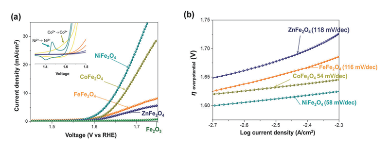
Figure 11 Electrochemical performance and gas evolution for a series sample of MFe2O4 (M = Fe, Co, Ni, Zn). (a) LSV curves were performed in alkaline electrolyte (0.5 M KOH). Insert: Cyclic voltammogram of each sample. (b) Steady-state Tafel (overpotential vs log current) measurements in alkaline electrolyte (0.5 M KOH).
Therefore, it seemed that the divalent metal is still the active site for OER, while the crystallographic sites should be the minor effect toward the performance. However, the divalent metal ions were placed at the different environments in the structure, indicating that the behavior would be different in the normal spinel structure. Furthermore, in-situ grazing-angle X-ray diffraction was used to figure out this issue. When the OER is beginning, both CoFe2O4 and NiFe2O4 exhibited a new peak at Q = 1.4 Å−1 with increasing the applied voltage (Figure 12), indicating that the formation of metal oxyhydroxide was a similar behavior to that of Co3O4[21][21] Van der Ven, A.; Morgan, D.; Meng, Y. S.; Ceder, G.: J. Electro. Soc. 153 (2006) A210-A215.. In contract to these two samples, Fe3O4 and ZnFe2O4 lacked of any new feature peak or any shift in position at higher voltage (Figure 13), which can explicate the different behavior from the electrochemical observation. The CV curves reveal the oxidation peaks should be referred to the phase transformation into metal oxyhydroxide, and the observations from Tafel slope suggested that the activity of electrocatalysts should refer to this structural transformation. As a result, the occurrence of present structural transformation toward metal oxyhydroxide is the key to dominate the activity of OER. In the cases of both CoFe2O4 and NiFe2O4, the divalent metal ions onto the surface will transform into metal oxyhydroxide, and then the metal oxyhydroxide on the surface will act as the main active phase for OER[22][22] Hsu, C. S.; Suen, N. T.; Hsu, Y. Y.; Lin, H. Y.; Tung, C. W.; Liao, Y. F.; Chan, T. S.; Sheu, H. S.; Chen, S. Y.; Chen, H. M.: Phys Chem Chem Phys 19 (2017) 8681-8693..
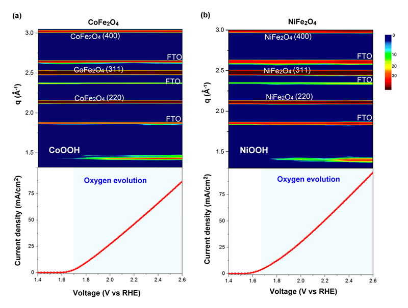
Figure 12 Contour plots of in-situ grazing angle X-ray diffraction signals of CoFe2O4 and NiFe2O4 samples in an aqueous solution containing 0.5 M KOH, and corresponding measured current density as function of applied voltage in both cases. The images show the diffraction intensity (color-coded) as a function of voltage, and data collection was performed by using 12 KeV of energy.
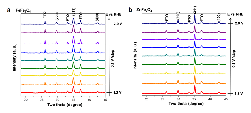
Figure 13 In-situ XRD spectra of (a) FeFe2O4 (b) ZnFe2O4 samples, a KOH electrolyte of 0.5 M was employed and all measurements with a potential range from 1.2 to 2.0 V vs RHE were operated potentiostatically.
Conclusion
In summary, we have provided several systems to understand the operating of spinel structure metal oxides during OER, and have demonstrated the in-situ XAS and in-situ grazing-angle X-ray diffraction to achieve this goal. First, CoO-modified Co3O4 with reversible junction layer results in a fact that the phase transformation becomes easier and make the electrocatalysts more stable. Second, NiCo2O4 was utilized as a model to realize the active site within the structure for bimetallic spinel oxide, in which Ni is the main active center while Co might not contribute to the reaction. For the influence upon the oxidation state of electrocatalysts toward OER, two metal ions, Zn and Al, well-known as non-active metal for OER were employed to substitute for the different oxidation states (i.e., Co2+ and Co3+) in spinel structure. The result can reveal that the divalent metal ions are the active metal. For the effect of crystallographic site, we choose Fe3O4 with inverse spinel system as a model to address this issue, in which the replacement of the Fe(II) with a series of divalent metal ions to clarify the activities at octahedral site. At the end, we can further confirm that the divalent metal ion is the active site regardless of crystallographic sites. The most importantly, to achieve the excellent activity toward OER, the divalent metal ion has to be transformed into metal oxyhydroxide that is the active phase for OER.
Acknowledgments
Beam time (BL12B2 and BL12XU) at SPring-8 was provided by NSRRC under Proposal 2016A4129, 2016B4129, 2017A4127, 2017A4132, 2017A4140, and 2017B4259. Financial support for this research was provided by MOST (104-2113-M-002-011-MY2).
References
[1] Rogner, H. H.: Annu. Rev. Energy Environ. 22 (1997) 217-262.
[2] Bert, G. D. a.; Miquel, A. G.-M.; Steve, P. L.: Annu. Rev. Plant Physiol. Plant Mol. Biol. 48 (1997) 609-639.
[3] Khan, S. U. M.; Al-Shahry, M.; Ingler, W. B.: Science 297 (2002) 2243-2245.
[4] Kudo, A.; Miseki, Y.: Chem. Soc. Rev. 38 (2009) 253-278.
[5] Bard, A. J.; Fox, M. A.: Acc. Chem. Res. 28 (1995) 141-145.
[6] Walter, M. G.; Warren, E. L.; McKone, J. R.; Boettcher, S. W.; Mi, Q.; Santori, E. A.; Lewis, N. S.: Chem. Rev. 110 (2010) 6446-6473.
[7] Suen, N. T.; Hung, S. F.; Quan, Q.; Zhang, N.; Xu, Y. J.; Chen, H. M.: Chem. Soc. Rev. 46 (2017) 337-365.
[8] Lee, Y.; Suntivich, J.; May, K. J.; Perry, E. E.; Shao-Horn, Y.: J. Phys. Chem. Lett. 3 (2012) 399-404.
[9] McCrory, C. C. L.; Jung, S.; Peters, J. C.; Jaramillo, T. F.: J. Am. Chem. Soc. 135 (2013) 16977-16987.
[10] Suntivich, J.; May, K. J.; Gasteiger, H. A.; Goodenough, J. B.; Shao-Horn, Y.: Science 334 (2011) 1383-1385.
[11] Sickafus, K. E.; Wills, J. M.; Grimes, N. W.: J. Am. Chem. Soc. 82 (1999) 3279-3292.
[12] Zhang, M.; de Respinis, M.; Frei, H.: Nat. Chem. 6 (2014) 362-367.
[13] Man, I. C.; Su, H.-Y.; Calle-Vallejo, F.; Hansen, H. A.; Martínez, J. I.; Inoglu, N. G.; Kitchin, J.; Jaramillo, T. F.; Nørskov, J. K.; Rossmeisl, J.: Chem. Cat. Chem. 3 (2011) 1159-1165.
[14] Tung, C.-W.; Hsu, Y.-Y.; Shen, Y.-P.; Zheng, Y.; Chan, T.-S.; Sheu, H.-S.; Cheng, Y.-C.; Chen, H. M.: Nat. Comm. 6 (2015) 8106.
[15] Trotochaud, L.; Ranney, J. K.; Williams, K. N.; Boettcher, S. W.: J. Am. Chem. Soc. 134 (2012) 17253-17261.
[16] Butel, M.; Gautier, L.; Delmas, C.: Solid State Ionics 122 (1999) 271-284.
[17] Subbaraman, R.; Tripkovic, D.; Chang, K. C.; Strmcnik, D.; Paulikas, A. P.; Hirunsit, P.; Chan, M.; Greeley, J.; Stamenkovic, V.; Markovic, N. M.: Nat. Mater. 11 (2012) 550-557.
[18] Wang, H. Y.; Hsu, Y. Y.; Chen, R.; Chan, T. S.; Chen, H. M.; Liu, B.: Adv. Energy Mater. 5 (2015) 1500091.
[19] Wang, H.-Y.; Hung, S.-F.; Chen, H.-Y.; Chan, T.-S.; Chen, H. M.; Liu, B.: J. Am. Chem. Soc. 138 (2016) 36-39.
[20] Szotek, Z.; Temmerman, W. M.; Ködderitzsch, D.; Svane, A.; Petit, L.; Winter, H.: Phys. Rev. B 74 (2006) 174431.
[21] Van der Ven, A.; Morgan, D.; Meng, Y. S.; Ceder, G.: J. Electro. Soc. 153 (2006) A210-A215.
[22] Hsu, C. S.; Suen, N. T.; Hsu, Y. Y.; Lin, H. Y.; Tung, C. W.; Liao, Y. F.; Chan, T. S.; Sheu, H. S.; Chen, S. Y.; Chen, H. M.: Phys Chem Chem Phys 19 (2017) 8681-8693.
BL12XU and B2 are opened for international users. Scientists who have been interested in the experiments described in this article may consider a submission of proposals to NSRRC, Taiwan (http://www.nsrrc.org.tw). Proposal calls are made three times a year, typically, June, October, and February. It is welcome to discuss the availability of experiments prior to the submission.
Contacts :
Nozomu Hiraoka, (NSRRC)
XU Spokesperson
hiraoka@spring8.or.jp
Hirofumi Ishii, (NSRRC)
B2 Spokesperson
h_ishii@spring8.or.jp
Yen-Fa Liao, (NSRRC)
B2 Operation manager
liao.yenfa@nsrrc.org.tw
Masato Yoshimura, (NSRRC)
XU Operation manager
yoshimur@spring8.or.jp