Volume 07, No.4 Pages 238 - 241
2. 共用ビームライン/PUBLIC BEAMLINE
The current status of BL28B2 for multi-purpose white x-ray diffractions
[1]JASRI Materials Science Division、[2]JASRI Beamline Division、[3]RIKEN Harima Institute
- Abstract
- BL28B2 is a beamline for multi-purpose experiments using white x-rays and has been opened to the public since the 9th cycle of 1999. The equipment in the optics hutch 2 was primarily optimized for a state-of-the-art x-ray diffraction imaging including white x-ray topography. In this report we describe the current status of the beamline, the experimental appliances for topography and some experimental results.
1. Introduction
BL28B2 is a beamline for experiments using white x-rays. The beamline provides high energy white x-rays with small divergence. A state-of-the-art x-ray diffraction imaging including white x-ray topography, a structural study of expanded fluid metals over the critical point at high pressure and high temperature and an energy dispersive XAFS (DXAFS) measurement are carried on.
The beamline was completed in the 8th cycle of 1999 and opened to the public since the 9th cycle of 1999. White x-ray topography has been carried out in the optics hutch (OH) 2.
At the end of December 2001, OH 3 was completed. OH 3 was added for a structural study of expanded fluid metals over the critical point at high pressure and high temperature. The high pressure equipment was moved from BL04B1 in February 2002. BL28B2 was closed during the 3rd cycle of 2002 for the renewal of the safety interlock system. Performance test and experiments using standard samples are now on the way in OH 3. A test of DXAFS measurements was also started in OH 3.BL28B2 has no double crystal monochromator nor x-ray mirrors. The major componets in the OH 1 are a water-cooled transport channel slit and a screen monitor. One can directly use white synchrotron radiation form a bending magnet source in OH 2 or OH 3. The specification of the beamline was briefly described by Goto et al. [1] [1]S. Goto et al. : SPring-8 Information, 4 (1999) 53.. The horizontal beam divergence is restricted to 1.2 mrad and, hence, the maximum beam size at 44 m from a light source is 10 mm (V)×53 mm (H). The early status of the experimental station (OH 2) was described previously [2] [2]Y. Yamazaki et al. : SPring-8 Information, 5 (2000) 23.. In this report we represent the current status of the beamline, the equipment and introduce some outputs.
2. Current status of BL28B2
2-1. Facilities in optics hutch 2
The equipment in OH 2 is optimized for a state-of-the-art white x-ray topography [3] [3]Y. Chikaura et al. : SPring-8 User Experiment Report No.4 (1999B) 148.. Installed are an attenuator unit, a water filter unit, a high speed shutter, a chamber for an optical component and a multi-purpose diffractometer.
The attenuator unit is adopted for the purpose of reducing radiation damage of samples and to improve the signal to noise ratio. The unit consists of six water-cooled metal plates : 15-mm-thick Pb, 2-mm-thick Al, 5-mm-thick Al, 1-mm-thick Cu, 2-mm-thick Cu and 1-mm-thick Fe, the usage of which are controlled through PC. 15-mm-thick Pb is used as an x-ray shutter and others are used to cut low energy x-rays. The minimum exposure time with the shutter is 0.1 sec. The air inside the unit is substituted by helium gas to prevent metal plates from oxidation.
The water filter unit is also used to reduce damage of samples, especially organic crystals [4] [4]K. Izumi et al. : SPring-8 User Experiment Report No.5 (2000A) 231.. The path length of water can be varied to optimize the image quality for each sample.
The high speed shutter enables one to get a topograph of a sample under time-varying condition without a fog. The unit consists of three tantalum blades of 5 mm thickness. The three blades are used to obtain uniform exposure time over the maximum aperture size of 5 mm × 5 mm. The blades are rotated by rotary solenoid motors and the shutter has the minimum exposure time of 1 msec +_ 1μsec [5] [5]K. Kajiwara et al. : SPring-8 User Experiment Report No.6 (2000B) 108.. The high speed shutter is used together with the shutter in the attenuator unit because 5-mm-thick tantalum blades are insufficient to stop high energy x-rays.
A chamber which contains an optical component is available for experiments using quasi-monochromatic x-rays. At the moment, a 111 reflection of silicon single crystal is equipped. We plan to use an oscillating crystal to monochromate x-rays with energy band width ∆E/E of 0.01 ~ 0.001. We are also planning to install a Bragg diffraction or a trasmission mirror of multilayers with wide energy band width of 0.5. The exit window of the chamber is made of aluminum foil, A scattering angle 2θ ranges from 0° to 30°.
The multi-purpose diffractometer is the main equipment of OH 2. The diffractometer can hold systems weighting 100 kg to the limit, such as a cryostat, a high temperature sample stage or others. One can mount various detectors within 20 kg to the detector arm. The detailed specification of the diffractometer was described previously [2] [2]Y. Yamazaki et al. : SPring-8 Information, 5 (2000) 23.. The diffractometer moves horizontally to accord the rotation axis to the beam in using quasi-monochromatic x-rays.
2-2. Improvement
Besed on the experience for earlier commissioning, a common stage for the equipment in OH 2 was devised. There had been a problem that each equipment had been set on the respective stage with a small weight capacity. This made it difficult to cover equipment with heavy radiation shields for reducing background. To settle the problem, the equipment excluding the multi-purpose diffractometer was set on a common stage with capacity of a few of tons in August 2001. As the aperture size of the high speed shutter was a diameter of 10 mm and the shutter was fixed on the floor, one could not use a larger beam than the aperture. Then the high speed shutter was set on a stage which moves vertically. When using the shutter, the stage is set to the upper side. When not using the shutter, the stage is set to the lower side and one can use larger beam than the aperture of the shutter. The shutter was covered with lead of 5 mm thickness at the same time. As casters were attachted to the common stage, one can carry the stage out from the hutch and also set to the same position. This enables users to bring a large instrument in OH 2. A huge wall of steel and lead of 5 mm thickness was made. One can set the wall between the chamber and the multi-purpose diffractometer to reduce background.
The high speed shutter has renovated to operate with a frequency of 5 Hz. This renovation enables one to take a topograph of varying phenomena on an x-ray film which is shifted synchronized with the shutter operation.
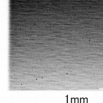
Fig.1 shows the direct beam profile recorded on an x-ray film. Many horizontal lines due to the roughness of the upstream Be window are seen. Though we had changed the Be window installed in the transport channel to mirror-polished ones with help of Front End Group, the lines still remained. This beam structure affects topograph of protein crystals. At this moment, there is no solution other than using a diffuser ; for example let x-rays pass the rotating sand papers. The same problem also arises at BL20B2.

Fig.1 Photograph of a direct beam. The exposure time was 1 msec. Many horizontal lines due to Be windows are seen.
2-3. Sample environment in optics hutch 2
One of the advantages of using white x-ray is the continuous observation of diffractions even if the temperature of a sample changes. To exploit this advantage, a high temperature sample stage and a cryostat is used.
The high temperature sample stage is installed in a vacum chamber for white x-ray topography technique. A sample is heated with infrared ray guided through a water-cooled quartz rod from a halogen lamp with the maximum power of 2 kW. The halogen lamp is fixed at one of the focal points of an ellipsoidal mirror and the end of quartz rod at the other focal point. The sample holder is also made by quartz. Two halogen lamps can be attached to the chamber. The chamber has three Be windows, one for incident beam, and the others for diffracted beams. The diffracted beam in a range of scattering angles of 22 ~ 58° and 94 ~ 130° can be measured through the Be windows. The available temperature ranges from room temperature to about 1700 K [6] [6]Y. Chikaura et al. : SPring-8 User Experiment Report No.6 (2000A) 227..
The cryostat system is also available for white x-ray topography technique. White x-ray topographs at the temperature of liquid helium 4.2 K were taken [7] [7]T. Ozaki et al. : SPring-8 User Experiment Report No.6 (2000A) 225..
2-4. Some of the outputs
Some results of the experiments performed at BL28B2 : a typical Laue topograph of dislocations, an x-ray scattering topograph using a microbeam, and a microangiographic image are shown below.
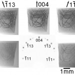
Laue topograph of two inch φ as-grown CZ Si is shown in Fig.2. These are the characteristic Laue topographs of dislocations. One can observe many diffraction spots at a time and can see the difference of the contrast of dislocations for each diffraction vector g.

Fig.2 Laue topographs of necking part of two inch ø as-grown CZ Si. Dislocation elimination by necking process is clearly seen. The contrast of dislocations is different for each g vector.
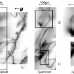
Fig.3 shows an x-ray scattering topograph of a 220 reflection Germanium single crystal with a 60 keV microbeam taken by Prof. Chikaura et al. [8] [8]Y. Chikaura et al. : SPring-8 User Experiment Report No.7 (2001A) 135.. The microbeam was produced by a collimator with a radius of 5 μm in a 15-mm-thick lead block. A Germanium solid state detector was used.
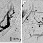
Fig.4 shows microangiographic images of the coronary arteries in a rat heart observed by Dr. Umetani et al. [9] [9]K. Umetani et al. : SPring-8 User Experiment Report No.8 (2001B) in press.. The experiments were done using a 111 reflection of silicon single crystal with x-ray energy of iodine absorption edge 33.17 keV.

Fig.3 X-ray scattering topographs of a 220 reflection Germanium single crystal with a 60 keV microbeam [8] [8]Y. Chikaura et al. : SPring-8 User Experiment Report No.7 (2001A) 135.. These images clearly reveal individual dislocations.
(a) Image size : 50 x 50 pixels, a scanning step interval : 10 µm.
(b) Image size : 40 x 40 pixels, a scanning step interval : 5 µm.
(c) Image size : 40 x 80 pixels, a scanning step interval : 5 µm.
(d) Image size : 80 x 80 pixels, a scanning step interval : 2 µm.
(e) Image size : 40 x 65 pixels, a scanning step interval : 2 µm.

Fig.4 Microangiographic images of the left coronary arteries in a rat heart under Langendorff perfusion at (a) baseline and (b) acetylcholine stress [9][9]K. Umetani et al. : SPring-8 User Experiment Report No.8 (2001B) in press.. Black arrowheads indicate apparent vasodilatation in response to acetylcholine. Vasodilatation was observed in small arteries with less than approximately 100 µm diameter.
3. Summary
BL28B2 is a significant beamline with the advantage of direct usage of white synchrotron radiation from a bending magnet source.
The equipment in OH 2 have been developed to perform experiments using white x-ray diffraction, especially white x-ray topography for the third generation synchrotron radiation. The attenuator unit is used as a shutter or to improve the signal to noise ratio. The fast shutter with the minimum exposure time of 1 msec can be used to observe varying phenomena. Samples can be cooled down to 4.2 K and heated up to 1700 K. A fluorescent screen, an Imaging Plates (IP), an x-ray visicon camera, and a beam monitor can be selected for imaging. Dark room facilities for developing x-ray films and nuclear emulsion plates is also available.
The equipment in OH 3 has been developed for a structural study of expanded fluid metals over the critical point at high pressure and high temperature. Performance test and experiments using standard samples are now on the way in OH 3 and remarkable results will be expected in the near future.
Acknowledgments
We are grateful to many staff members of SPring-8, FE Group, Optics and Transport Channel group, Control Group, Radiation Physics Group, and Accelerator Division. Special thanks are to the members of Topograph Sub Group for their continuous support. We thanks to Prof. Y. Chikaura and Dr. K. Umetani for providing experimental results. We also thank Dr. M. Yamakata for his arrangements for OH 3. Y. I. would like to acknowledge Dr. O. Sakata for reading the manuscript.
References
[1]S. Goto et al. : SPring-8 Information, 4 (1999) 53.
[2]Y. Yamazaki et al. : SPring-8 Information, 5 (2000) 23.
[3]Y. Chikaura et al. : SPring-8 User Experiment Report No.4 (1999B) 148.
[4]K. Izumi et al. : SPring-8 User Experiment Report No.5 (2000A) 231.
[5]K. Kajiwara et al. : SPring-8 User Experiment Report No.6 (2000B) 108.
[6]Y. Chikaura et al. : SPring-8 User Experiment Report No.6 (2000A) 227.
[7]T. Ozaki et al. : SPring-8 User Experiment Report No.6 (2000A) 225.
[8]Y. Chikaura et al. : SPring-8 User Experiment Report No.7 (2001A) 135.
[9]K. Umetani et al. : SPring-8 User Experiment Report No.8 (2001B) in press.
Yasuhiko IMAI
Materials Science Division, Japan Synchrotron Radiation Research Institute
1-1-1 Kouto Mikazuki-cho Sayo-gun Hyogo 679-5198 Japan
TEL : (+81) 791-58-0832 FAX : (+81)791-58-0830
e-mail: imai@spring8.or.jp


