Volume 06, No.6 Pages 450 - 455
2. 共用ビームライン/PUBLIC BEAMLINE
The current status of BL13XU for surface and interface structures
[1]JASRI Materials Sciences Division、[2]JASRI Beamline Division、[3]JASRI Materials Sciences Division and JASRI Beamline Division、[4]SPring-8 Service Co. Ltd.、[5]JASRI Beamline Division and RIKEN Harima Institute
- Abstract
- BL13XU is currently being prepared for public use. We would bring you to a guided tour of BL13XU. The beamline monochromator and mirrors have been tested. Thus x-ray beam performance has been evaluated. We describe herein the topics (a photon flux, intensity stability, the critical angles of the mirror, and a focal condition) out of outcomes that we have achieved since May 2001. Diffractometers available are mentioned as well.
1. Introduction
BL13XU is going to be dedicated to a research of two-dimensional crystallography with atomic-scale resolution. To perform diffraction/scattering from a surface, one can use an ultrahigh vacuum (UHV) chamber mounted on a huge diffractometer in the end station (experimental hutch (EH) 3). A feature is combination of up-to-date techniques of synchrotron-radiation diffraction/scattering and state-of-the-art surface science facilities. On top of that, a multi-axis diffractometer in EH 1 is available for an atomic-scale-structural study of an interface. Construction of an insertion device (ID), front-end components, optics and a transport channel, hutches, and utilities was successfully finished in the end of March 2001. Design of the beamline was briefly described by Goto et al. [1] [1]S. Goto, K. Takeshita, and T. Ishikawa : SPring-8 Information, 5 (2000) 100. (the design values will be compiled in the forthcoming SPring-8 Beamline Handbook). Performance test of BL13XU has started since May 2001. The beamline is partially opening for public use from September 2001 and will be fully available from 2002 A user-beam time.
2. Description of the beamline
The light source is the standard SPring-8 in-vacuum undulator [2] [2]H. Kitamura : J. Synchrotron Rad. 7 (2000) 121. of 32 mm period and its number of 140. The gap of the ID are opened up to 50 mm and closed down to 9.6 mm. The fundamental energy range available is correspondingly from 18.9 to 5.5 keV. Figure 1 depicts the beamline layout. The beamline double crystal monochromator with an Si 111 reflection is cooled down with a liquid nitrogen chiller [3] [3]The following article does not describe the chiller for BL13XU but for a similar one. T. Mochizuki et al. : Nucl. Inst. and Meth. A 467-468 (2001) 647.. Two mirrors have two rows of a rhodium (Rh) coating and a platinum (Pt) coating material with a Cr binder. They are for rejecting harmonics of incident photons and for focusing an x-ray beam in a horizontal scattering geometry. The beamline has three EH's. The multi-axis diffractometer in EH 1 is positioned 63 m from the source and the diffractometer for the UHV chamber in EH 3 is placed at a distance of 73 m from the source.
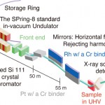
Fig. 1 Layout of BL13XU. The inside of EH 3 is additionally illustrated.
2-1. Positions of a front-end (FE) slit
We made lateral and vertical scans of an FE slit with an aperture of 0.5 mm2 to determine a center of an x-ray beam. An ID gap used was 21 mm. Default zero positions in both directions looked all right. For fine adjustment of a vertical position of the FE slit, we swept an incident photon energy by adjusting the monochromator at four vertical positions of the FE slit (Fig. 2). An ID gap of 50 mm was used. Intensity curves recorded were drastically changed in shape. The curve for a vertical position of zero gave a peak at the highest energy. This is a good way to confirm the proper vertical position zero of the FE slit, which was suggested by Dr. Yabashi.
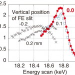
Fig. 2 Energy scans for four vertical positions of an FE slit. The solid line is for clarification. A vertical aperture used was 0.5mm.
2-2. X-rays from the monochromator : a photon flux and stability
We measured spectrum with a silicon pin photo diode (Hamamatsu Photonics K.K. S3590-09) for a dozen of different ID gaps. Figure 3 plots a fundamental and a third peak intensity with an incident photon energy. The data were followed by correction of absorption of a 150 µm-thick Be window of the photo diode.
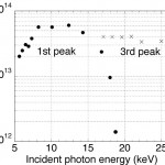
Fig. 3 An absolute x-ray photon flux measured. An FE slit opening used was 1 × 1 mm2.
We also observed intensity stability for a 1×1 mm2 aperture of the FE slit and a photon energy of 16.9 keV (See an example shown in Fig. 4). This intensity decay stemmed from change in a temperature of the second monochromator stage. This is because Compton scattering from the first monochromator crystal gave an additional heat load to the stage. The intensity was more stable as the temperature reached a constant value. When using a 0.5×0.5 mm2 opening, we found that we had a constant intensity within about 5% except for the first two hours after electron injection to the storage ring. Such instability about the liquid-nitrogen-cooled monochromator at BL29XUL/19LXU was reported by Dr. Tamasaku et al [4][4]K. Tamasaku, M. Yabashi, T. Mochizuki, and T. Ishikawa : SPring-8 Information, 6 (2001) 390.. We plan to put a Cu or a Pb shield between the first and the second crystal stage during the next beam break. It is noted that the FWHM angular width of a rocking curve was here 4.6 arc sec while a calculated one was 4.4 arc sec. This implies the monochromator crystal was considerably perfect and the deviation was probably due to vibration.
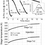
Fig. 4 X-ray intensity stability vs. time. An FE slit aperture used was 1 × 1 mm2.
2-3. The mirrors : the critical angle (φc) for total external reflection and a focal condition
We recorded four sets of reflectivity curves from the Rh (upper row) and the Pt row (lower one) as a function of an incidence angle (φ) at four incident photon energies. Figure 5 shows a measured φc with an incident wavelength. A slop of a fitted line is in proportion to a square root of a density of a coating material. We thus evaluated the densities, 12 and 16 g/cm3 for a Rh and a Pt coating material respectively. (The values were 96% and 73% of a net density of a Rh and a Pt bulk respectively.) Figure 5 would be on tap when one sets a φ angle for a given incident photon energy. An 80% of the φc value would be appropriate to reject harmonics.
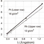
Fig. 5 The critical angle (φc) for total external reflection as a function of an incident wavelength(λ). The lines fitted reach the origin of the graph.
We counted x-ray intensities with a slit scanning at a fixed bend pulse. The slit was positioned at a distance of 15.8 m downstream from the second mirror [5] [5]The slit used was a variable-aperture type. We set its lateral opening of about 0.5 mm but we did not calibrate the width, which was found to be less than 0.5 mm from the results shown in Fig. 6.. Figure 6 shows an FWHM spatial beam width in a lateral direction as a function of a bend pulse. The bend pulse for the narrowest width decreased with a φ value (also shown in Fig. 7). The mirror was presumably flat at a bend pulse of 3.87×10⁵ (a y-intercept value N0). It had a 6.7 km-radius of a curvature at a bend pulse equal to zero accordingly if we assume that the mirror had a ellipsoid shape and was bent without any force. We, however, supposed that an unexpected force could be applied when installing the mirror since the radius (6.7 km) was very small compared with a radius (>40 km) which was reported in the inspection data.
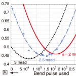
Fig. 6 A measured FWHM beam size 15.8 m downstream from the second mirror. The curves are fitted lines. 凹 stands for a shape of a reflecting surface of the mirror.
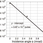
Fig. 7 A bend pulse for focusing. The fitted line is shown as well.
A radius of curvature R is expressed as R = ![]() .
.
Here p is a distance from a light source to a mirror considered and q is a distance between the mirror and a focal point. p is not always a distance from the ID to the mirror. The distance (p = pa = 55.7 m in our case) is the maximum value. Imagine that a very tiny FE slit aperture like a pinhole in a lateral direction could be a new light source. Such situation would give p = pb = 25.7 m. The radius R can be approximately written using bend pulse number NB as follows : ![]() By comparison of two expressions of R for two φ's, we obtained two experimental R's : R [m] =
By comparison of two expressions of R for two φ's, we obtained two experimental R's : R [m] =![]() -89.3 and R [m] =
-89.3 and R [m] =![]() -71.2. Figure 8 plots a calculated focal distance q which is expressed as q =
-71.2. Figure 8 plots a calculated focal distance q which is expressed as q = ![]() . We have two focal positions so far. One is for the multi-axis diffractometer in EH 1 and the other is for the UHV chamber in EH 3. Figure 8 would be on hand when one finds a desirable bend pulse. The difference of the focal distance (between the solid and the broken lines) is less than 1 m at the respective focal position.
. We have two focal positions so far. One is for the multi-axis diffractometer in EH 1 and the other is for the UHV chamber in EH 3. Figure 8 would be on hand when one finds a desirable bend pulse. The difference of the focal distance (between the solid and the broken lines) is less than 1 m at the respective focal position.
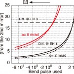
Fig. 8 A calculated focal distance of the second mirror vs. a bend pulse with three values of φ. The solid lines for p = 55.7m and the broken ones are for p = 25.7m (in an ultimate case) where p is defined in the text.
3. Facilities available
Representative facilities are a pack of three UHV chambers and the multi-axis diffractometer. The UHV chambers are being made ready. The multi-axis diffractometer was moved from BL09XU to EH 1. Capabilities of the instruments include x-ray scattering studies in grazing incidence, studies of crystal truncation rods, reflectivity measurements, x-ray standing waves, and many others in UHV and in air.
3-1. UHV chambers
The chambers will be independently coupled to a six-circle diffractometer (Fig. 9) (3.2 m × 3.2 m × 2.3 m in size). The diffractometer has 2 degrees of freedom (DOF) on a sample and 2 fully independent DOF on an x-ray detector. Examples of measurements that will be expected are the following; observation of a dynamic change in an atomic structure at a crystal surface (such as phase transition and an initial stage of thin-film growth), and analysis of a super structure at the surface.
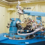
Fig. 9 A UHV chamber mounted on a six-circle diffractometer, which is called the 'Ao- Dohyo' of 'Smo' or the blue mammoth in EH 3.
Figures 10, 11, and 12 represent the chambers drawn from an x-ray diffraction point of view. A feature of Chambers 1 and 2 is that a sample surface normal is parallel to the principal axis ω (this is called a Z sample geometry). On the other hand, a sample surface is parallel to the axis ω in chamber 3. Chamber 2 has a sample holder that can cover a remarkably wide range of temperatures from 20 - 2000 K. The ω axis of Chamber 3 provides us with a precise rotation of a sample.
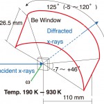
Fig. 10 Chamber 1.
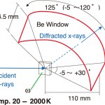
Fig. 11 Chamber 2.
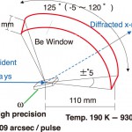
Fig. 12 Chamber 3.
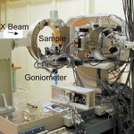
Fig. 13 A multi-axis diffractometer in EH 1.
3-2. Multi-axis diffractometer
The diffractometer had been used at BL09XU. We just introduce the first reflectivity data that Prof. Isao Takahashi's group took at BL13XU in the end of Sept. 2001 (Fig. 14). The data has an ample reflectivity range (more than 10 orders of magnitude) for atomic-scale-structural analysis of a surface layer.
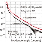
Fig. 14 A typical reflectivity curve. An incident photon energy used was 12.1 keV
4. Things to do
First of all, we must make the UHV chambers ready as soon as possible. We, moreover, need to collect information on stability of a photon energy as well as an intensity from the monochromator. If needed, we will change the monochromator stage. The key attitude to bear in mind is that we should communicate efficiently with BL19LXU, BL20XU, BL29XUL, and BL35XU people who have experienced this problem.
It is timely to start thinking a project of scientific impact suitable for the third generation synchrotron radiation.
Acknowledgments
We never forget the beam line is being supported by the ID Group, FE Group, Optics and Transport Channel Group, Control Group, Radiation Physics Group, and Accelerator Division. Sakata has been very impressed by the SPring-8 standard system that consists of the excellent accelerator, perfect insertion devices, complete frontends, beatiful monochromators and mirrors, and the sophisticated control systems. Ms. T. Hirono and Mr. K. Kato aligned TC slits in off-line. We discussed the monochromator with Drs. K. Tamasaku and M. Yabashi. The software program for converting a detector current to an absolute intensity was provided by Dr. M. Yabashi. Dr. Y. Fukumoto, Messrs. H. Murakami, T. Matsumoto, and Ms. M. Koike gave technical support. Mr. T. Ohashi prepared drawings of Figs. 10, 11, and 12. Perpetual suggestions and encouragement are given by Drs. H. Suematsu and T. Ueki.
References
[1]S. Goto, K. Takeshita, and T. Ishikawa : SPring-8 Information, 5 (2000) 100.
[2]H. Kitamura : J. Synchrotron Rad. 7 (2000) 121.
[3]The following article does not describe the chiller for BL13XU but for a similar one. T. Mochizuki et al. : Nucl. Inst. and Meth. A 467-468 (2001) 647.
[4]K. Tamasaku, M. Yabashi, T. Mochizuki, and T. Ishikawa : SPring-8 Information, 6 (2001) 390.
[5]The slit used was a variable-aperture type. We set its lateral opening of about 0.5 mm but we did not calibrate the width, which was found to be less than 0.5 mm from the results shown in Fig. 6.
Corresponding author
坂田 修身 SAKATA Osami
(財)高輝度光科学研究センター 放射光研究所 利用促進研究部門I
TEL:0791-58-0832 FAX:0791-58-0830
e-mail:o-sakata@spring8.or.jp
