


Volume6 No.2
SPring-8 Section C: Technical Report
Optimization of the KB Mirror Installation at BL35XU
aJapan Synchrotron Radiation Research Institute (JASRI)
bRIKEN SPring-8 Center
- Abstract
-
BL35XU is a high resolution inelastic scattering beamline for measuring atomic dynamics of materials using X-rays. Typical beam size for inelastic X-ray scattering experiments at BL35XU is 60 to 100 µm diameter using a bent-cylindrical mirror. BL35XU sometimes operates with a smaller beam for measurements of small samples such as samples installed in diamond anvil cells. KB mirrors have been used for such experiments since 2007. However, since ~2012, the time required for KB installation has increased, sometimes to as much as 2 days. In order to reduce the time for installation of the KB mirrors and clarify the problems during the installation, we investigated and resolved the problems related to installation of the KB mirrors.
Keywords: KB mirror installation, inelastic X-ray scattering
Background
BL35XU [1] operates as a public beamline for inelastic X-ray scattering (IXS) with a beam size that tends to be ~60 to 100 µm in diameter, depending on the details of the setup. This beamline has been used mainly for measuring atomic dynamics in crystalline and disordered materials. Meanwhile, number of experimental proposals in geoscience, which needs investigation of materials under high pressures, >100 GPa, and high temperatures, >3000 K, have been increasing. About a third of total delivered beamtime has been occupied by geoscience and related scientific fields. Since diamond anvil cells are used as a high pressure apparatus in such scientific field, typical sizes of samples, especially at higher pressures, are often much smaller than the nominal beam size at BL35XU. Therefore, operation with smaller beam size at BL35XU has been required in experiments related to geoscience
BL35XU employed Kirkpatrick-Baez (KB) mirror in Ref. 2 to measure small samples such as the samples inserted into DAC’s. KB setup designed beam size focused down to 15 µm diameter at the sample position of the BL35XU spectrometer. When we used 21.747 keV X-ray, the focused beam size was reported as about 15 vertical x 16 horizontal µm2 [2]. At BL35XU of SPring-8, the horizontal sample position is fixed, because the BL35XU spectrometer cannot be moved horizontally. This means that installation of the KB setup requires that the incident beam be moved to focus correctly onto the sample position of the BL35XU spectrometer.
It took two or three days to install the KB mirror setup since 2012, although it took less time before 2012. In order to optimize the KB setup with reasonable time, we investigate the origin of failure to optimize it within a day or so, and learn the optimization of the KB mirror setup. This investigation was performed with 17.793 keV of X-rays, which is usually for DAC studies.
Optimization of KB mirror installation
Beam focusing at BL35XU is realized by a compound setup of a bent cylindrical mirror and KB mirrors as shown in Fig. 1. The beam is over-focused by the bent cylindrical mirror and the KB mirrors are aligned to X-ray beam. When the KB mirrors are used, beam path is different from that in normal use without the KB mirrors: there is a shift in the vertical which is compensated by spectrometer alignment as shown in Fig. 1(a). However, in the horizontal, the fixed scattering center of the large, 10 m, two-theta-arm means that the incident beam must be shifted to keep the horizontal beam position at the sample unchanged as shown in Fig. 1(b). This requires complete re-alignment of the beamline focusing optics. In order to install and optimize the KB mirror setup quickly, positions of the KB mirrors must include motion range of the translation stages both with and without use of the KB mirrors and be well controlled with reproducibility.
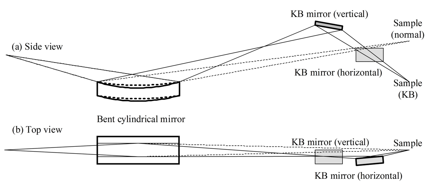
Fig. 1. Schematic drawing of focusing setup at BL35XU. Solid (Dotted) line depicts X-ray in use of (without) KB mirror.
The situation from 2012 on was aggravated by two issues: one was disagreement with the movable ranges of translation stages for the KB mirrors; the other is loss of reproducibility of some slits, used as a reference for the X-ray beam position in the normal setup, located at the upstream from the KB setup. The former is caused by long-term drift of the backscattering angle of the high resolution monochromator. The latter is caused by loss of reproducibility of the incident slit owing to hardening of grease on translation stages for incident beam slit. To resolve the former problem, we tune the backscattering angle of high resolution monochromator to δ = 0.3 mrad, where 2δ is defined as the angle difference between incoming beam and scattering beam directions, before aligning the KB mirror setup. To resolve the latter problem, the grease from the translation stages was replaced.
The results obtained in this investigation are shown in Fig. 2. The measurements were carried out by knife edge scan using a gold wire with 200 µm diameter. The obtained beam size reaches 15 vertical x 16 horizontal µm2, which is a typical beam size delivered to experiments related to geoscience using Si(9 9 9) backscattering setup at BL35XU at present.
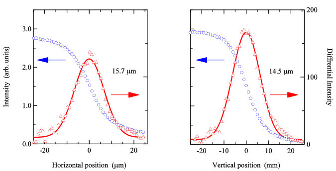
Fig. 2. Beam profiles focused by the combination of the KB mirrors with the bent-cylindrical mirror at BL35XU.
Blue circles depict data taken by Au wire edge scans. Red triangles are the difference and a fit (solid line).
Summary
This work enabled the time for the setup of the spectrometer for small samples to be reduced to ~1 day (~24 hours), including both the installation of the KB setup and the spectrometer re-alignment, after it had become longer and longer and longer beginning in ~2012. Issues relating to drift of the backscattering angle to achieve high-energy resolution setup for IXS and grease hardening which hurt the reproducibility of translation stages for slits
Acknowledgements
We thank Dr. Naomi Kawamura for suggestion of a tool for Au wire edge scan.
Reference
[1] A. Q. R. Baron, Y. Tanaka, S. Goto, K. Takeshita, T. Matsushita, and T. Ishikawa, J. Phys. Chem. Solids 61, 461 (2000).
[2] D. Ishikawa, H. Uchiyama, S. Tsutsui, H. Fukui, and A. Q. R. Baron, Proc. SPIE 8848, 8848F (2013).
ⒸJASRI
(Received: June 6, 2017; Early edition: January 31, 2018; Accepted July 3, 2018; Published August 16, 2018)