


Volume4 No.2
SPring-8 Section C: Technical Report
Feasibility Study of a Diffraction Grating as a Soft X-ray Beam Splitter toward Soft X-ray Fourier Transform Spectroscopy
Utilization Frontier R&D Group, Research & Utilization Division ,JASRI
- Abstract
-
With the aim of performing Fourier transform spectroscopy in the soft X-ray region, we examined the feasibility of a conventional diffraction grating as a beam splitter in the wavelength range of 1–10 nm. The basic idea of the present research is that the divided positive- and negative-order diffraction beams can be used in X-ray interferometric experiments. We performed a beam-dividing test using a diffraction grating. The grating parameter was chosen by taking into account the geometrical restriction for the negative-order diffraction and the equivalent diffraction efficiency for both light orders. However, we could not detect the negative-order light by using the selected diffraction grating.
Keyword: Soft X-ray interferometer, beam splitter, diffraction grating
Background and Purpose:
Undulators have been utilized in third-generation light sources in worldwide synchrotron radiation facilities owing to their high brilliance in the short-wavelength region. Highly brilliant light sources allow the use of well-focused soft X-ray beams with high photon flux, which are necessary to operate soft X-ray grating monochromators at the maximum resolving power. As a result, the resolution of soft X-ray monochromators has been dramatically improved, making it possible carry out soft X-ray spectroscopic experiments with an excitation photon bandwidth narrower than the natural width of the inner-shell excited states [1]. One of the motivations for improving soft X-ray spectrometers relates to the unique capabilities of resonant inelastic X-ray scattering (RIXS) spectroscopy, which is essentially unrestricted by the natural line width. RIXS projects target high-resolution spectroscopy combined with a bandwidth on the order of sub-meV to clarify various elemental excitations. Until now, monochromators using diffraction gratings have been utilized in soft X-ray spectroscopy and a number of monochromators have been designed over several decades. However, it appears that the theoretical maximum resolving power of a grating monochromator is insufficient for such high-resolution measurements [2]. Therefore, to achieve a higher resolving power, an approach other than the traditional grating-based monochromator must be used.
Interferometers are known to exceed grating monochromators in terms of their maximum resolving power. Therefore, interferometric techniques have long been utilized in infrared spectroscopy and, more recently, in the visible and near-UV regions [3]. In the interferometer, the spectral resolution is determined by the difference in the number of waves in the two interfering beams passing an unequal route. This path difference is determined by the design of the mechanical system, and ordinarily, the moving mirror produces the path difference. Good performances are obtained by controlling the path difference, which is needed to achieve the required resolving power. For example, the expected resolving power for a 1.2 mm path difference is 1 × 10⁶ at 0.6 nm (at oxygen K-edge). Furthermore, the next generation of synchrotron sources, known as "diffraction-limited storage rings," will produce fully coherent radiation in the soft X-ray region. The highly coherent flux makes it possible to apply interferometric techniques such as high-resolution spectroscopic measurements. Thus, it would be interesting to consider the possibility of achieving better resolution by introducing interferometers in the soft X-ray region.
The main goal of our research is to develop a two-beam interferometer achieving Fourier transform spectroscopy to obtain higher resolution than that of the grating monochromator in the soft X-ray region. The basic operation of a Fourier transform spectrometer is to divide an incident beam into two parts and to recombine them coherently after introducing a phase delay. The Fourier transform of the resulting interference pattern, as a function of the path-length difference, yields the energy spectrum of the incident beam. In the interferometric measurements, the beam splitter is a key component in the X-ray region. In practice, interferometry with X-rays is very difficult to execute because of the short wavelengths involved. Only recently have optical technologies advanced sufficiently to make the construction of an X-ray interferometer practical [4] . In the vacuum ultraviolet (VUV) region, a wave-division-type beam splitter has been proposed and interferometric measurements have been conducted [5] . However, interferometry in the soft X-ray region is significantly behind that in the UV and hard X-ray regions given the limitation of practical optics. In this research, we propose the use of a conventional diffraction grating as a beam splitter. In the present report, we describe the basic concept of the beam splitter and the result of our initial beam deviation measurements.
Experimental Summary:
The basic idea of "the diffraction grating beam splitter" is explained in the schematic drawing shown in Figure 1. A general form of the grating equation for use with monochromators is given by
2dsin(α + β) = mλ, ・・・ (1)
where λ is the wavelength of the incident light, and α and β are the angles between the incident and diffracted rays with respect to the grating normal vector, respectively. d is the glove number of the grating and m is an integer representing the order of interest (which can be either positive or negative). In a soft X-ray monochromator, it is necessary to have either positive- or negative-order light, but not both. Commonly, the positive-order light is used to obtain dispersive light, whereas the negative order light is rarely used. In other words, in spite of using the setup as a beam splitter, the separated beam is generally not used for measurement purposes. If we can handle these two splitting beams, we can apply them to interferometric experiments in the soft X-ray region. One of the advantages of this experimental setup is that a conventional grating can also be adapted for the beam splitter. Since we can use the grating not only for the conventional monochromator but also as an interferometer, it is unnecessary to develop novel optics for interferometric measurements.

Figure 1: Schematic layout of diffraction grating beam splitter.
When designing the diffraction grating for the beam splitter, there are two significant points for the determination of the grating parameter. The first point is a geometrical restriction to eject the negative-order light from the grating surface. Figure 2 shows the diffraction angle as a function of incident photon energy obtained for four different incident angles. For example, when we choose 83.5° as the incident angle, the diffraction angle becomes greater than 90° below 460 eV. In this situation, the negative-order light cannot be ejected from the grating surface. Figure 2 indicates that the available energy range for a beam splitter becomes narrower at the grazing incident layout. In the present beam-dividing measurement, we used 680 eV photons and the grating was mounted at 83.5° with respect to the incident photon beam.
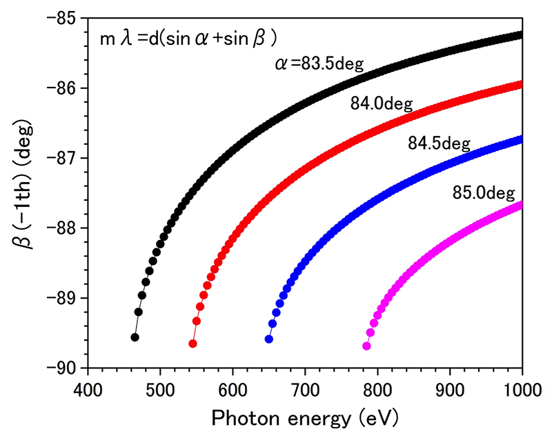
Figure 2: Diffraction angle of the grating simulated at four different incident angles. The groove density was fixed at 1200 l/mm.
The second point is the diffraction efficiency for each order of light. When a diffraction grating with a shallow groove for which the shadow effect can be ignored is used, the relative diffraction efficiency of laminar-type diffractive gratings is given by
E(λ,m) = 4sin2[πh(cosα + cosβ)/λ]/(mπ)2, ・・・ (2)
where h denotes the groove depth [6].
Figure 3 exhibits the simulated diffraction efficiency of the grating (Shimadzu Co.:30-001) at an incident angle of 83.5°. One characteristic feature indicated in Fig. 3 is that the diffraction efficiency differs for each order of light. In the lower-photon-energy region, the diffraction efficiency of the negative-order light is higher than that of the positive-order light. However, the diffraction efficiency of the negative-order light sharply decreases with increasing incident photon energy. The efficiency of both orders of the X-ray beam becomes equivalent at approximately 685 eV. This simulation suggests that this grating is unfavorable for use as a beam splitter because the energy region where equivalent diffraction efficiency is obtained is quite narrow. However, the diffraction efficiency can be optimized to be equivalent by choosing an appropriate number of grooves and depth; therefore, this problem is solvable. In this study, we used a commercially available grating, because we needed to assess the feasibility of our idea before producing a dedicated grating for the beam splitter. In the present preliminary measurement, we performed the beam division test at 680 eV using the above-mentioned grating.
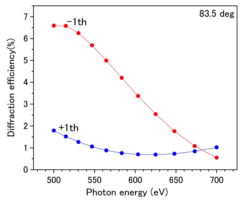
Figure 3: Simulated diffraction efficiency for the grating used in the beam-dividing experiment. The grating parameters are summarized in Table 1.
| Specification | |
|---|---|
| Manufacturer | Shimadzu Co. |
| Order number | 30-001 |
| Master/replica | Replica |
| Type of groove | Laminar |
| Groove depth (nm) | 8.5 |
| Groove density (l/mm) | 2400 |
| Base | BK7 |
For the beam-splitting experiment, a laminar-type reflective grating was installed after the post-focusing mirror and the monochromatized soft X-ray beam was further divided by a second grating. The measurements were taken at a photon energy of 680.0 eV, and the photon energy band path was fixed at 45 meV. The beam shape at the second grating was circular and the spot size was approximately 500 μm in diameter with a photon flux of 1 × 10¹¹ photons/s. The grating was installed in the vacuum chamber (1 × 10⁻⁶ Pa) and mounted on an XYZϑ stage for alignment with the incident beam. The direct and dispersed beams were visually observed using a CeYAG scintillator crystal, and the divided photon intensity was determined using a Si-PIN photodiode detector.
Results and Discussion:
The incident angle was set at 83.5° and the divided beam was visually monitored on the Ce:YAG scintillator located 250 mm downstream from the grating. Figure 4 shows the visual observation of the divided beam on the scintillator. When the grating acts effectively as the beam splitter, we can expect to observe a bright spot (0th-order light) and indistinct spots (±1st-order light), which are located on either side of the 0th-order light. While we can confirm the total-reflection beam (0th-order light), an indistinct spot was observed only on the 1st-positive-order side, but not on the negative-order side.
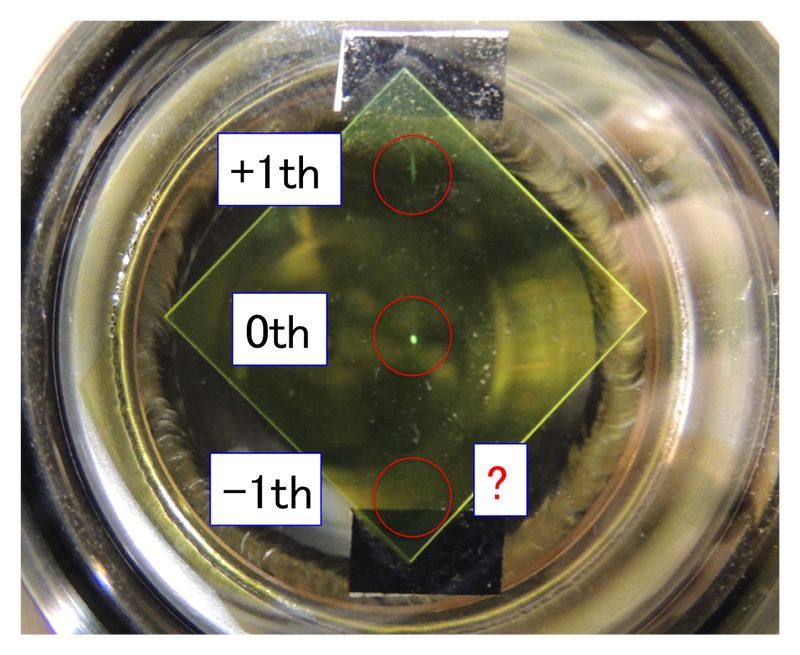
Figure 4: Visual observation of divided beam on Ce:YAG scintillator.
Figure 5 shows the photon intensity distribution measured at 250 mm downstream from the grating. We can observe two peaks whose intensities are largely different. The distance between the two peaks is of about 13 mm, which is consistent with the expected relative position between 0th- and +1st-order light. Therefore, the main peak can be attributed to the 0th-order light, and the small peak appearing on the right side is attributed to the +1st-order light. However, while the –1st-order light should be observed in a position symmetrically opposed to that of the +1st-order light with respect to the 0th-light, the negative-order light could not be detected.
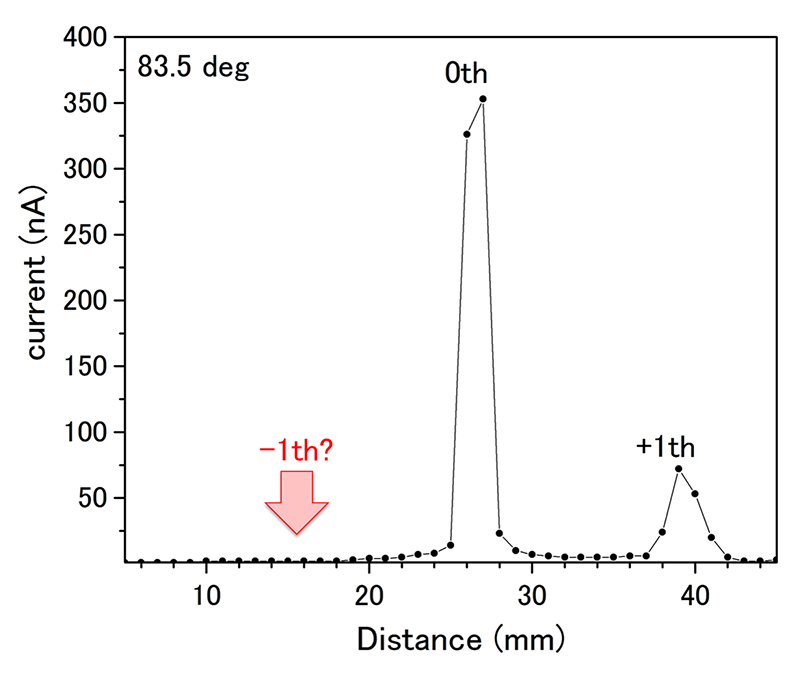
Figure 5: Intensity distribution of divided beam.
It can be confirmed that the selected grating works as a beam splitter, because the 0th-order light and the +1st-order light were observed in the expected locations. Furthermore, we searched for the –1st-order light by changing the incident angle in the range 88–83° as well as the incident energy in the range of 400–800 eV with the same setup. However, it was not possible to detect the negative-order light by using this diffraction grating.
Challenges:
In this work, we could not observe the –1st-order light in the present beam-dividing test. The grating was selected by taking into account the geometrical restrictions for the negative-order light and giving the equivalent diffraction efficiency. The results of preliminary simulations have also been verified by the manufacturer of the grating and we expected to observe both positive and negative diffraction beams, as well as the total-reflection light. Therefore, the exact reason why the negative-order light did not appear is unclear. We need to revise the simulation program by consulting with the manufacturer of the grating. We will continue to investigate beam-dividing measurements by using a grating with different parameters in order to better understand its properties.
Acknowledgements:
This work was financially supported by the SOLUTUS project in SPring-8. The author gratefully acknowledges the SOLUTUS committee for the opportunity to make this work possible and for advice during the review process.
References:
[1] N. Mårtensson, O. Karis and A. Nilsson, J. Electr. Spectrosc. Relat. Phenom. 100, 379 (1999).
[2] V. N. Strocov et al., J. Synchrotron Rad. 17, 631 (2010).
[3] N. de Oliveira, M. Roudjane1, D. Joyeux, D. Phalippou, J.-C. Rodier and L. Nahon, Nature Photonics 5, 149 (2011).
[4] M. Yabashi, K. Tamasaku, and T. Ishikawa, Phys Rev. Lett. 87, 140801 (2001); M. Yabashi, K. Tamasaku, and T. Ishikawa, Phys. Rev. A 69, 023813 (2004).
[5] M. R. Howells, K. Frank, Z. Hussain, E.J. Moler, T. Reich, D. Moller, and D. A. Shirley, Nucl. Instr. and Metho. A. 347, 182-191 (1994); H. Yin, M. Wang, M. Strom, and J. Nordgren, Nucl. Instr. and Metho. A. 451, 529 (2000); E. J. Moler, et al., J. Electr. Spectrosc. Relat. Phenom. 80, 309 (1996); Ochi et al., Jpn. J. Appl. Phys. 51, 016601 (2012).
[6] A. Frank, et al., Phil. Trans. Roy. Soc, Ser A, 277, 503 (1975).
©JASRI
(Received: March 29, 2016; Early edition: June 15,2016; Accepted: June 24, 2016; Published: July 25, 2016)